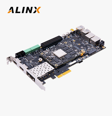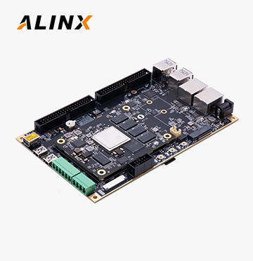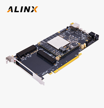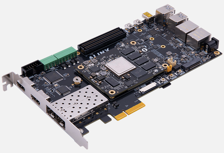

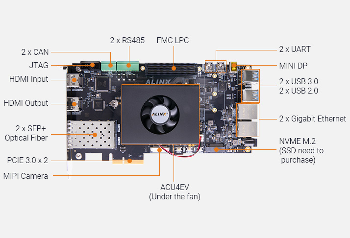

The AXU4EVB-P development board equipped with the AMD/ Zynq™ UltraScale+™ MPSoC-series device, delivers standout performance with DDR4 SDRAM, eMMC Flash, QSPI Flash, PCIe, FMC LPC, SFP+, M.2, DPCAN/RS485, suitable for Artificial Intelligence, Computing, Automotive, Industrial, Video, and Communication, etc.
Unit price
$ 885In stock:
>9, ready to ship in 2 workdays

The AXU4EV/5EVB-P development board equipped with the AMD/Xilinx Zynq™ UltraScale+™ MPSoC-series device, delivers standout performance with fast DDR4 SDRAM, eMMC Flash, QSPI Flash, PCIe, FMC LPC, DP, HDMI, M.2, CAN, RS485.
Compatible with a multitude of FMC board (data acquisition, motor control, display camera interfaces, software defined radio), Provide high-speed communication (SFP+), high-speed storage (M.2) and video applications (DP, HDMI).
● Artificial Intelligence
● Automotive
● AV Broadcasting
● Deep learning
● Digital Signal Processing
● 5G Wireless and Wire Communication
● Data Centers
● Drive / Motion Control
● Industrial Internet of Thing
● Cloud Computing Security
● Machine Vision
● Medical Endoscop
● Video and Image Processing
Design-in Kit – The Fast Way to the Market, to get started with development straight out of the box.
The ALINX development board help shorten time-to-market for any AMD/Xilinx Zynq™ UltraScale+™ MPSoC based application.

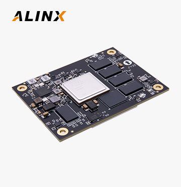
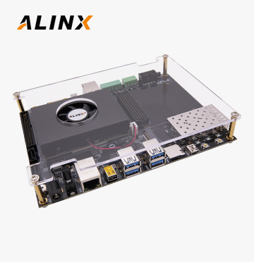
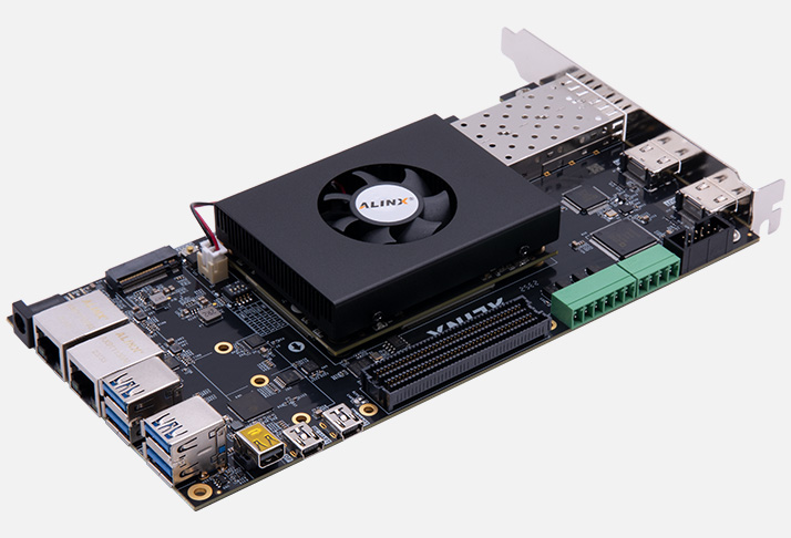
* The AXU4EVB-P development board consists of a ACU4EV SoM and base board. If you want to purchase ACU4EV SoM separately.
Please check the Relevant Products at the bottom of the page and click to learn more details.
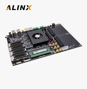
The FAN8060 Heatsink Kit is an optimal cooling solution for ALINX FPGA and SoC modules – it is low-profile and covers the whole module surface.
| System-on-Module | 1 | Base Board | 1 |
|---|---|---|---|
| Heatsink Kit (preinstalled) | 1 | USB Downloader Cable / set | 1 |
| 12V Power Adapter | 1 | PCle Fence | 1 |
| Mini USB Cable | 1 | Card Reader | 1 |
| TF Card | 1 |
1. For non-preferred models, a minimum order quantity (MOQ) may apply if the products are not in stock.
2. We offer custom configuration, a MOQ applies.
Please contact us for more details.
We offer complete documentations and a lot of demos and tutorials.
Please contact us should you have any need.
AXU4EVB-P User Manual
2024-02-29Links: AMD Pangomicro AUMO Autonomous Driving


Alinx Electronic Limited 沪ICP备13046728号
Please verify your email address by getting a code before downloading.