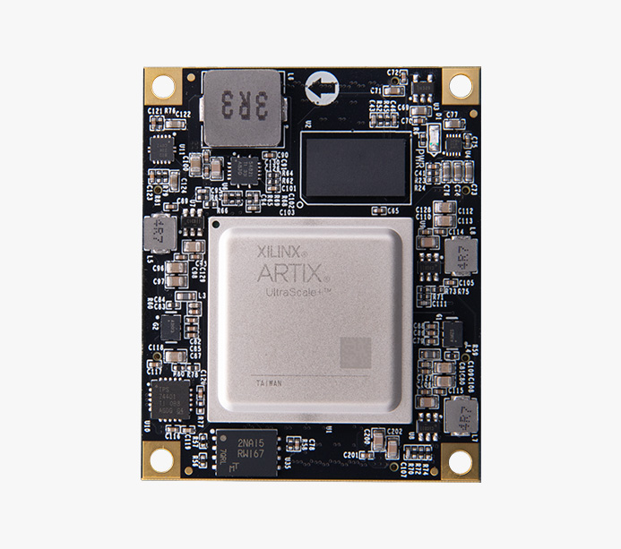

XCAU15P
Model
ACAU15Price
$ 317
The Artix UltraScale+device adopts a 16 nanometer architecture, achieving excellent performance to power ratio. Artix UltraScale+FPGA provides transceivers with speeds up to 12.5Gb/s for advanced protocols, supporting strong DSP computing processing capabilities, matching I/O bandwidth with computing, providing superior system performance for cost sensitive low-power applications, fully meeting the needs of machine vision, security networks, 4K broadcasting, and various industrial IoT and edge markets.
170K
156K
78K
12.5Gb/s x12
32MB QSPI FLASH
1GB DDR4 32bit


*Learn about the corresponding development board, click to view details>>
Core board model
ACAU15
Chip model
XCAU15P-2FFVB676I
Operation temperature
Industrial grade, -40°C~85°C
RAM
1GB DDR4, 16bit
QSPI FLASH
32MB
System Logic Cells
170K
CLB Flip-Flops
156K
CLB LUTs
78K
Max. Distributed RAM
2.5Mb
Total Block RAM
5.1Mb
Clock Mgmt Tiles
3
DSP Slices
576
PCI Express
PCIE 4.0
GTH transceivers
GTH 12.5Gb/s x12
HD IOs
72
HP IOs
102
LVDS
48
DDR4
One 1GB DDR4 storage chip with a data rate of up to 2400Mbps
QSPI Flash
1 QSPI FLASH chip with a size of 32MB, storing FPGA configuration Bin files and other user data files.
Clock configuration
1 200MHz differential crystal oscillator that can provide reference clocks for DDR4 controllers and FPGA logic
1 156.25MHz differential crystal oscillator for reference clock input of GTH transceiver
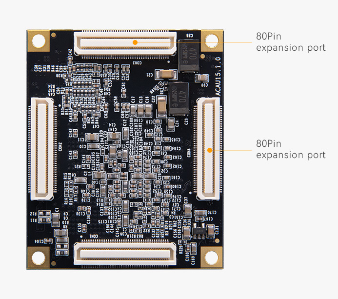
80 Pin expansion port
4 high-speed expansion ports, connected to the backplane using 4 80Pin inter board connectors, and the IO ports of the FPGA are connected to these 4 expansion ports through differential cabling
LED
1 is the power indicator light (PWR)
INPUT VOLTAGE
+12V, powered by connecting the backplane
Core board
1
Size
55mm x 45mm x 6.8mm
Number of layers
Adopting a 14 layer PCB design with reserved independent power layer and GND layer

Structural dimension diagram
Provide Schematic, PCB, Size Dimension, Package and Reference Design, that to Accelerate the Development of products with Core Board

Provide schematic diagrams (. pdf), PCB structure diagrams (. pdf), packaging, reference designs, etc. for ease of secondary development

Network Communication

Data Center Networking and Storage Acceleration

Medical Imaging

Industrial Automation

Video Imaging

IOT

ATE

Machine Vision
The warranty period of all products sold is 12 months, of which FPGA chips and LCD screens are wearing parts and are not covered by the warranty. All accessories and gifts are not covered under warranty.